
Unit:
|

Unit:
|
3. 公差
产品等级A、C和F级的垫圈公差见表1。
除非另有规定,本部分规定的公差适用于垫圈表面处理前尺寸。
仅当有正当的技术原因时,允许本部分规定的垫圈公差与产品标准不同;当本部分与产品标准规定的公差不同时,应以后者为准。
形状和位置公差的规定和表示方法按GB/T 1182和GB/T 16671。
3.1 通孔d 1
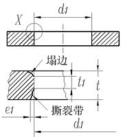
厚度 | 公差 | ||||||
产品等级 | |||||||
F | A | C | |||||
t<2 2≤t<4 t≥4 | d 1 公差 | t 1 min | e 1 max | d 1 公差 | t 1 min | e 1 max | d 1 公差 |
H12 | 0.5 t | 0.10 t | H13 | 0.3 t | 0.15 t | H14 | |
H12 | 0.3 t | 0.15 t | H13 | 0.25 t | 0.20 t | H14 | |
H13 | 0.2 t | 0.20 t | H14 | 0.2 t | 0.25 t | H15 | |
塌边尚未定义,但允许存在 | 撕裂带(e 1)、t 1和塌边尚未定义,但允许存在 | ||||||
t 1是在d 1规定公差范围内孔的部分 | |||||||
3.2 外径d 2
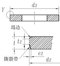
厚度 | 公差 | ||||
产品等级 | |||||
F | A | C | |||
t<2 2≤t<4 t≥4 | d 2 公差 | e 2 max | d 2 公差 | e 2 max | d 2 公差 |
h13 | 0.13 t | h14 | 0.18 t | h16 | |
h13 | 0.15 t | h14 | 0.20 t | h16 | |
h14 | 0.18 t | h15 | 0.25 t | h16 | |
塌边和t 2尚未定义,但允许存在 | 撕裂带(e 2)、t 2和塌边尚未定义,但允许存在 | ||||
t 2是在d 2规定公差范围内外径的部分 | |||||
3.3 厚度t

厚度公差应在去除毛刺后测量
厚度t | 产品等级 | ||
F | A | C | |
t≤0.5 | ±0.04 | ±0.05 | ±0.10 |
0.5<t≤1 | ±0.06 | ±0.10 | ±0.20 |
1<t≤2.5 | ±0.12 | ±0.20 | ±0.30 |
2.5<t≤4 | ±0.16 | ±0.30 | ±0.60 |
4<t≤6 | ±0.20 | ±0.60 | ±1.00 |
6<t≤10 | ±0.24 | ±1.00 | ±1.20 |
10<t≤20 | ±0.28 | ±1.20 | ±1.60 |
3.4 倒角
3.4.1 外倒角c 2
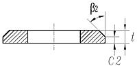
3.4.2 内倒角c 1

公称厚度 | 产品等级 | |||||
F | A | C | ||||
c 1 min | c 2 min | c 1 min | c 2 min | c 1 min | c 2 min | |
1≤t<2 | 0.20t | 0.25t | 0.20t | 0.25t | 0.20t | 0.25t |
2≤t<4 | 0.18t | 0.22t | 0.18t | 0.22t | 0.18t | 0.22t |
t≥4 | 0.15t | 0.20t | 0.15t | 0.20t | 0.15t | 0.20t |
3.4.3 组合垫圈补充可选择要求
当买方要求时,倒角的位置相对于冲压过程产生的偏差应在订货时指定。

3.5 形状和位置公差
3.5.1 同一位置厚度偏差Δt
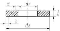
Δt要求适用于x = 0.1(d2-d1)以外的部位,即仅圆环宽度的60%。
厚度t | 产品等级 | ||
F | A | C | |
Δt max | Δt max |
| |
t≤0.5 | 0.020 | 0.025 | 无要求 |
0.5<t≤1 | 0.030 | 0.050 | |
1<t≤2.5 | 0.060 | 0.100 | |
2.5<t≤4 | 0.080 | 0.150 | |
4<t≤6 | 0.100 | 0.200 | |
6<t≤10 | 0.120 | 0.300 | |
10<t≤20 | 0.140 | 0.400 | |
3.5.2 同轴度y
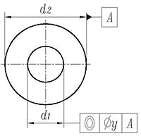
厚度t | 产品等级 | ||
F | A | C | |
y max | y max | y max | |
t<2 | 2IT11 | 2IT12 | 2IT13 |
2≤t≤4 | 2IT12 | 2IT13 | 2IT14 |
t≥4 | 2IT13 | 2IT14 | 2IT15 |
公差 y 基于直径 d 2 | |||
3.5.3 平面度(挠度)z

平面度(挠度)z是垫圈有效高度h eff 和垫圈有效厚度t eff之差。
注1:z的公差与厚度公差互为独立公差。
注2:附加工艺,如磨削,可能要求更小的挠度。
平面度公差应在去除毛刺后测量。
厚度t | 产品等级 | ||
F | A | C | |
z | z | z | |
t≤0.5 | 0.07 | 0.10 | 0.13 |
0.5<t≤1 | 0.10 | 0.15 | 0.20 |
1<t≤2.5 | 0.20 | 0.20 | 0.25 |
2.5<t≤4 | 0.30 | 0.30 | 0.30 |
4<t≤6 | 0.40 | 0.40 | 0.40 |
6<t≤10 | 0.60 | 0.60 | 0.60 |
10<t≤20 | 1.00 | 1.00 | 1.00 |
Geometrical Product Specifications (GPS) - ISO code system for tolerances on linear sizes - Part 1: Basis of tolerances, deviations and fits
Geometrical product specifications ( GPS ) - ISO code system for tolerances on linear sizes - Part 2: Tables of standard tolerance classes and limit deviations for holes and shafts
Steel die forgings - Tolerance and machining allowance

Tolerences for fasteners-Bolt/nut assemblies for service temperatures from -200℃~+700℃

Tolerances for fasteners - Bolts,screws,studs and nuts
Geometrical tolerancing - Geometrical tolerance for features wlthout individual tolerance indications
Tolerances for fasteners Bolts 、screws and nuts for fine mechanics

Tolerances for fasteners - Part 3: Plain washers for bolts,screw and nuts - Product grades A, C and F

Tolerances for fasteners— Part1:Bolts,screws,studs and nuts—Product grades A,B and C
Aerospace - Bolts and screws, metric - Tolerances of form and position
General tolerances - Tolerances for linear and angular dimensions without individual tolerance indications
Geometrical tolerancing - Geometrical tolerance for features wlthout individual tolerance indications
Tolerances for fasteners - Part 2 : Bolts, screws and nuts with thread diameters from 1 up to 3 mm and product grade F, for fine mechanics
General tolerances - Tolerances for linear and angular dimensions without individual tolerance indications
Dimensions and tolerances of bright steel products

Hot rolled steel plate 3 mm thick or above Tolerances on dimensions, shape and mass
Technical Supply Conditions For Threaded Steel Fasteners - Part 2 Tolerances For Fasteners - Bolts, Screws, studs And Nuts - Product Grades A, B And C
Length Tolerances for Bolts [TABLE 13]
