|
|

Unit:
|
|
|
|
Unit:
|
3.1 应力截面积的计算,见下面公式,如无特殊要求,取3位有效数字。
 或 As = 0.7854(d-0.9382P)2
式中:As ——螺纹的应力面积,mm2;
d——外螺纹大径的基本尺寸,mm;
d2——螺纹中径的基本尺寸,mm;
d3——螺纹小径的基本尺寸(d1)减去螺纹原始三角形高度(H)的1/6值,即:![]() mm;
mm;
H——螺纹原始三角形高度(H = 0.866025P),mm;
P——螺距,mm;
π——圆周率,π= 3.1416。
3.2 应力截面积值
对粗牙螺纹M1~M68(GB 193)、细牙螺纹M8×1~M130×6(GB 193)的应力截面积(As)值,如下表所示。
粗牙螺纹 | 细牙螺纹 | ||||
螺纹直径d mm | 螺距P mm | 应力截面积AS mm2 | 螺纹直径d mm | 螺距P mm | 应力截面积AS mm2 |
1 | 0.25 | 0.46 | 8 | 1 | 39.2 |
1.1 | 0.25 | 0.588 | 10 | 1 | 64.5 |
1.2 | 0.25 | 0.732 | 10 | 1.25 | 61.2 |
1.4 | 0.3 | 0.983 | 12 | 1.25 | 92.1 |
1.6 | 0.35 | 1.27 | 12 | 1.5 | 88.1 |
1.8 | 0.35 | 1.7 | 14 | 1.5 | 125 |
2 | 0.4 | 2.07 | 16 | 1.5 | 167 |
2.2 | 0.45 | 2.48 | 18 | 1.5 | 216 |
2.5 | 0.45 | 3.39 | 20 | 1.5 | 272 |
3 | 0.5 | 5.03 | 20 | 2 | 258 |
3.5 | 0.6 | 6.78 | 22 | 1.5 | 333 |
4 | 0.7 | 8.78 | 24 | 2 | 384 |
4.5 | 0.75 | 11.3 | 27 | 2 | 496 |
5 | 0.8 | 14.2 | 30 | 2 | 621 |
6 | 1 | 20.1 | 33 | 2 | 761 |
7 | 1 | 28.9 | 36 | 3 | 865 |
8 | 1.25 | 36.6 | 39 | 3 | 1030 |
10 | 1.5 | 58 | 45 | 3 | 1400 |
12 | 1.75 | 84.3 | 52 | 4 | 1830 |
14 | 2 | 115 | 56 | 4 | 2144 |
16 | 2 | 157 | 60 | 4 | 2490 |
18 | 2.5 | 192 | 64 | 4 | 2851 |
20 | 2.5 | 245 | 72 | 6 | 3460 |
22 | 2.5 | 303 | 76 | 6 | 3890 |
24 | 3 | 353 | 80 | 6 | 4340 |
27 | 3 | 459 | 85 | 6 | 4950 |
30 | 3.5 | 581 | 90 | 6 | 5590 |
33 | 3.5 | 694 | 95 | 6 | 6270 |
36 | 4 | 817 | 100 | 6 | 7000 |
39 | 4 | 976 | 105 | 6 | 7760 |
42 | 4.5 | 1120 | 110 | 6 | 8560 |
45 | 4.5 | 1310 | 115 | 6 | 9390 |
48 | 5 | 1470 | 120 | 6 | 10300 |
52 | 5 | 1760 | 125 | 6 | 11200 |
56 | 5.5 | 2030 | 130 | 6 | 12100 |
60 | 5.5 | 2360 |
|
| |
64 | 6 | 2680 |
|
| |
68 | 6 | 3060 | |||
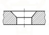
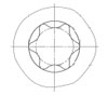
4.1 承载面积的计算涉及众多因素,如紧固件的支承面形状、尺寸、螺栓和螺钉通孔的大小、有无垫圈面或垫圈等。常用支承面形状的计算公式,如下表所示。如无特殊要求,取3位有效数字。
支承面的形状 | 承载面积的计算公式 |
圆 形 |
|
六角形 |
|
方 形 |
|
注:Ab1——圆形支承面的承载面积,mm2; Ab2——六角形支承面的承载面积,mm2; Ab3——方形支承面的承载面积,mm2; dw——支承面或垫圈面直径,mm2,见GB 5276; S——六角或方形的对边宽度,mm,见GB 5276; dh——螺栓或螺钉通孔直径,mm,按GB 5277选取; π——圆周率,π=3.1416。 | |
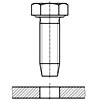
4.2 典型的螺纹紧固件的承载面积(Ab)值及承载面积(Ab)与应力截面积(As)之比(Ab/As以下简称面积比),如下图及表3~表5所示。

表3
螺纹紧固件 | 螺栓或螺钉 通孔直径dh mm | 面积比 Ab/As | |||
种类 | 对边宽度S mm | 垫圈面 | 螺纹公称直径d mm | ||
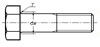
六角头螺栓 | 标准系列 | 无 | 3~80 | 按GB 5277 (无内倒角)或 GB 152.2~152.4 | 见表4 |
有 | |||||
加大系列 | 有 | 12~39 | |||
无 | |||||
内六角螺钉 | / | 无 | 1.6~36 | 见表5 | |
方头螺栓 | 标准系列 | 无 | 10~48 | ||
六角法兰面螺栓 | 标准系列 | 无 | 5~16 | ||
盘头螺钉 | / | 无 | 1.6~10 | ||
注: 1. 六角头螺栓的标准系列、加大系列,按GB 3104选取;方头螺栓按GB 8选取;内六角螺钉,按GB 70,选取,六角法兰面螺栓,桉GB 5787选取,盘头嫘钉,按GB 67或GB 818选取。 2. 当螺母支承面的形状、尺寸与表中六角头螺栓、方头螺栓、六角法兰面螺栓相同时,表4和表5也适用于该螺母。 | |||||
表4
螺纹规格 | 螺栓或 螺钉通孔直径dh mm | 六角头螺栓的承载面积与应力面积之比 | ||||||||||||
六角标准系列 | 六角垫圈面标准系列 | 六角加大系列 | 六角垫圈面加大系列 | |||||||||||
粗牙 | 细牙 | 对边宽度 S mm | 承载面积 Ab2 mm2 | 面积比 Ab2/AS | 支承面 直径 dw=0.95S mm | 承载面积 Ab1 mm2 | 面积比 Ab1/AS | 对边宽度 S mm | 承载面积 Ab2 mm2 | 面积比 Ab2/AS | 支承面 直径 dw=0.95S mm | 承载面积 Ab1 mm2 | 面积比 Ab1/AS | |
M3 | / | 3.4 | 5.5 | 17.1 | 3.4 | 5.22 | 12.3 | 2.4 | / | / | / | / | / | / |
M4 | / | 4.5 | 7 | 26.5 | 3 | 6.65 | 18.8 | 2.1 | / | / | / | / | / | / |
M5 | / | 5.5 | 8 | 31.7 | 2.2 | 7.6 | 21.6 | 1.5 | / | / | / | / | / | / |
M6 | / | 6.6 | 10 | 52.4 | 2.6 | 9.5 | 36.7 | 1.8 | / | / | / | / | / | / |
M7 | / | 7.6 | 11 | 59.4 | 2.1 | 10.45 | 40.4 | 1.4 | / | / | / | / | / | / |
M8 | M8×1 | 9 | 13 | 82.7 | 2.3(2.1) | 12.35 | 56.2 | 1.5(1.4) | / | / | / | / | / | / |
M10 | M10×1.25 | 11 | 16 | 127 | 2.2(2.1) | 15.2 | 86.4 | 1.5(1.4) | / | / | / | / | / | / |
M12 | M12×1.25 | 13.5 | 18 | 137 | 1.6(1.5) | 17.1 | 86.5 | 1(0.94) | 21 | 239 | 2.8 | 19.95 | 169 | 2 |
M14 | M14×1.5 | 15.5 | 21 | 193 | 1.7(1.5) | 19.95 | 124 | 1.1(0.99) | 24 | 310 | 2.7 | 22.8 | 220 | 1.9 |
M16 | M16×1.5 | 17.5 | 24 | 258 | 1.6(1.5) | 22.8 | 168 | 1.1(1.0) | 27 | 391 | 2.5 | 25.65 | 276 | 1.8 |
M18 | M18×1.5 | 20 | 27 | 317 | 1.7(1.5) | 25.65 | 203 | 1.1(0.94) | 30 | 461 | 2.4 | 28.5 | 324 | 1.7 |
M20 | M20×1.5 | 22 | 30 | 399 | 1.6(1.5) | 28.5 | 258 | 1.1(0.95) | / | / | / | / | / | / |
M20 | M20×1.5 | 22 | / | / | / | / | / | / | 34 | 621 | 2.5 | 32.3 | 439 | 1.8 |
M22 | M22×1.5 | 24 | / | / | / | / | / | / | 36 | 670 | 2.2 | 34.2 | 466 | 1.5 |
M22 | M22×1.5 | 24 | 34 | 549 | 1.8(1.6) | 32.3 | 367 | 1.2(1.1) | / | / | / | / | / | / |
M24 | M24×2 | 26 | 36 | 591 | 1.7(1.5) | 34.2 | 388 | 1.1(1.0) | 41 | 925 | 2.6 | 38.95 | 661 | 1.9 |
M27 | M27×2 | 30 | 41 | 749 | 1.6(1.5) | 38.95 | 485 | 1.1(0.98) | 46 | 1130 | 2.5 | 43.7 | 793 | 1.7 |
M30 | M30×2 | 33 | 46 | 977 | 1.7(1.6) | 43.7 | 645 | 1.1(1.1) | 50 | 1310 | 2.3 | 47.5 | 917 | 1.6 |
M33 | M33×2 | 36 | 50 | 1150 | 1.7(1.5) | 47.5 | 754 | 1.1(0.99) | 55 | 1600 | 2.3 | 52.25 | 1130 | 1.6 |
M36 | M36×3 | 39 | 55 | 1430 | 1.8(1.7) | 52.25 | 950 | 1.2(1.1) | 60 | 1920 | 2.4 | 57 | 1360 | 1.7 |
M39 | M39×3 | 42 | 60 | 1730 | 1.8(1.7) | 57 | 1170 | 1.2(1.1) | 65 | 2270 | 2.3 | 61.75 | 1610 | 1.6 |
M42 | / | 45 | 65 | 2070 | 1.8 |
| ||||||||
M45 | / | 48 | 70 | 2430 | 1.9 | |||||||||
M48 | / | 52 | 75 | 2750 | 1.9 | |||||||||
M52 | / | 56 | 80 | 3080 | 1.8 | |||||||||
M56 | / | 62 | 85 | 3240 | 1.6 | |||||||||
M60 | / | 66 | 90 | 3590 | 1.5 | |||||||||
M64 | / | 70 | 95 | 3970 | 1.5 | |||||||||
M68 | / | 74 | 100 | 4360 | 1.4 | |||||||||
/ | M72×6 | 78 | 105 | 4770 | (1.4) | |||||||||
/ | M76×6 | 82 | 110 | 5200 | (1.3) | |||||||||
/ | M80×6 | 86 | 115 | 5640 | (1.3) | |||||||||
注: 1. 螺栓或螺钉通孔直径dh,按GB 5277中等装配系列(无内倒角)的基本尺寸选取; 2. 对边宽度S,见六角支承面图,按GB 3104的基本尺寸选取; 3. 垫圈面直径dw,见六角垫圈面图,按dw=0.95S计算; 4. 括号内的面积比(Ab/AS)适用于细牙螺纹。 | ||||||||||||||
表5
螺纹 规格 | 螺栓或螺钉 通孔直径dh mm | 螺栓及螺钉的承载面积与应力截面积之比 | |||||||||||
内六角螺钉 | 方头螺栓 | 六角法兰面螺栓 | 盘头螺钉 | ||||||||||
支承面 直径dw mm | 承载面积 Ab1 mm2 | 面积比 Ab1/As | 对边 宽度S mm
| 承载面积 Ab3 mm2 | 面积比 Ab3/As | 支承面 直径dw mm | 承载面积 Ab1 mm2 | 面积比 Ab1/As | 支承面 直径dw mm | 承载面积 Ab1 mm2 | 面积比 Ab1/As | ||
M1.6 | 1.8 | 2.72 | 3.27 | 2.57 | / | / | / | / | / | / | 3.2 | 5.5 | 4.3 |
M2 | 2.4 | 3.4 | 4.56 | 2.2 | / | / | / | / | / | / | 4 | 8.04 | 3.9 |
M2.5 | 2.9 | 4.18 | 7.12 | 2.1 | / | / | / | / | / | / | 5 | 13 | 3.8 |
M3 | 3.4 | 5.07 | 11.11 | 2.21 | / | / | / | / | / | / | 5.6 | 15.6 | 3.1 |
M4 | 4.5 | 6.53 | 17.59 | 2 | / | / | / | / | / | / | 8 | 34.4 | 3.9 |
M5 | 5.5 | 8.3 | 30.35 | 2.14 | / | / | / | 9.4 | 45.64 | 3.2 | 9.5 | 47.1 | 3.3 |
M6 | 6.6 | 9.38 | 34.89 | 1.74 | / | / | / | 11.6 | 71.47 | 3.6 | 12 | 78.9 | 3.9 |
M8 | 9 | 12.33 | 55.79 | 1.52 | / | / | / | 14.9 | 110.75 | 3 | 16 | 137 | 3.7 |
M10 | 11 | 15.33 | 89.54 | 1.54 | 16 | 161 | 2.8 | 18.7 | 179.61 | 3.1 | 20 | 219 | 3.8 |
M12 | 13.5 | 17.23 | 90.02 | 1.07 | 18 | 181 | 2.1 | 22.6 | 258.01 | 3.1 |
|
|
|
M14 | 15.5 | 20.17 | 130.83 | 1.14 | 21 | 252 | 2.2 | 26.4 | 358.7 | 3.1 | |||
M16 | 17.5 | 23.17 | 181.11 | 1.15 | 24 | 335 | 2.1 | 30.6 | 494.89 | 3.2 | |||
M18 | 20 | / | / | / | 27 | 415 | 2.2 |
|
|
| |||
M20 | 22 | 28.87 | 274.48 | 1.12 | 30 | 520 | 2.1 | ||||||
M22 | 24 | / | / | / | 34 | 704 | 2.3 | ||||||
M24 | 26 | 34.81 | 420.77 | 1.19 | 36 | 765 | 2.2 | ||||||
M27 | 30 | / | / | / | 41 | 974 | 2.1 | ||||||
M30 | 33 | 43.61 | 638.4 | 1.14 | 46 | 1261 | 2.2 | ||||||
M33 | 36 | / | / | / | / | / | / | ||||||
M36 | 39 | / | 973.47 | 1.19 | 55 | 2170 | 2.7 | ||||||
M39 | 42 | / | / | / | / | / | / | ||||||
M42 | 45 | / | / | / | 65 | 2635 | 2.4 | ||||||
M45 | 48 | / | / | / | / | / | / | ||||||
M48 | 52 | / | / | / | 75 | 3501 | 2.4 | ||||||
M52 | 56 | / | / | / |
| ||||||||
注: 1. 螺栓或螺钉通孔直径db,按GB 5277中等装配系列(无内倒角)的基本尺寸选取; | |||||||||||||
Taper keys of keyways

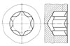
Hexalobular internal driving feature for bolts and screws
Fasteners-Ends of parts with external thread(ISO 4753:2011, MOD)
Fasteners - Bolts, screws and studs - Nominal lengths and thread lengths (ISO 888:2012, MOD)
Countersinks for countersunk head screws
Connections with waisted stud - Tape classification
Flared couplings - Flared end
Hexalobular internal driving feature for bolts and screws
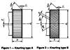
Knurl
Drill diameter for use prior to tapping screw threads
Square and rectangular keyways
Woodruff keyways
General purpose bolts and screws - Radius under the head
Center holes
Rivet Shank Diameters (Except Blind Rivets) [ISO 1051:1999]
Countersunk flat head screws - Part2: Penetration depth of cross recesses
Offset cruciform recess fro rotary fastening devices
Clearance holes for rivets
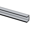
Hot-rolled channel steel
Hexagon lobuar for fasteners - Type E
Fasteners - Clearanc holes for bolts and screws
Fasteners - Split pin holes and wire holes (ISO 7378:1983)
Countersunk head screws - Head configuration and gauging
Cross recesses for screws
Fastners - Widths across flats of hexagon products
Self-tapping screws for metric ISO threads - Part 2: Guide values for hole diameters
Thread run-outs and thread undercuts
Tapping screw connections - Guideline values for core hole diameters and use
12 point socket for bolts and screws
60° centre holes - Types R. A. B. and C
Thread rolling screws for ISO metric thread guidelinge values for hole diameters
Thread ends and lengths of projection of bolt ends for metric ISO threads according to DIN 13
Knurle
Connections for hydraulic fluid power and general use - Ports and stud ends with ISO 261 metric threads and O-ring sealing - Part 1: Ports with truncated housing for O-ring

Hexalobular internal driving feature for bolts and screws
Connections for general use and fluid power - Ports and stud ends with ISO 228-1 threads with elastomeric or metal-to-metal sealing - Part 1: Threaded ports
Dimensioning and indication of knurling

Fasteners—Ends of parts with external ISO metric thread
Connections for general use and fluid power - Ports and stud ends with ISO 228-1 threads with elastomeric or metal-to-metal sealing - Part 4: Stud ends for general use only with metal-to-metal sealing (type B)
Hexalobular internal driving feature for bolts and screws
Geometrical product specifications (GPS) - Indication of surface texture in technical product documentation

General purpose bolts and screws─Metric series─Radii under the head

Rivet shank diameters
Aerospace - Spline drives - Wrenching configuration - Metric series
Connections for general use and fluid power - Ports and stud ends with ISO 261 threads with elastomeric or metal-to-metal sealing - Part 1: Threaded ports
Connections for general use and fluid power - Ports and stud ends with ISO 261 threads with elastomeric or metal-to-metal sealing - Part 2: Stud ends with elastomeric sealing (type E)
Connections for general use and fluid power - Ports and stud ends with ISO 261 threads with elastomeric or metal-to-metal sealing - Part 3: Stud ends with metal-to-metal sealing (type B)
Connections for general use and fluid power - Ports and stud ends with ISO 725 threads and O-ring sealing - Part 3: Light-duty (L series) stud ends

Fasteners—Surface discontinuities— Part2:Nuts

Countersunk flat hed screws—Part 2:Penetration depth of cross recesses

Fasteners—Surface discontinuities— Part1:Bolts,screws and studs for general requirements

Fasteners—Surface discontinuities— Part3:Bolts,screw and studs for special requirements
Internal drive, offset cruciform recess (Torq-Set) for rotary fastening devices. Metric series

Fasteners—Thread undercuts for external metric ISO
Cross recessed-H type
Cross recessed-Z type

Countersunk head screws—Head configuration and guaging

Fasteners—Hexagon products—Widths across flats

Fasteners─Clearance holes for bolts and screws
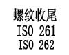
Thread run-out for fasteners with thread in accordance with ISO 261 and ISO 262
Copper tubes of circular section - Dimensions
Hexalobular internal driving feature for bolts and screws
Stress area and bearing area for threaded fasteners
General purpose bolts and screws - Metric series -- Radii under the head
Straight cylindrical involute splines -- side fit -- Generalities, dimensions and inspection
Knurling
Automatic Cold Header - Hole Size
Recess Dimensions for Flat 82° Countersunk Head Screws
Dimensions of Threads and Points for Types BF and BT Thread-Cutting Tapping Screws
Dimensions of Threads and Points for Type D, F, G, and T Thread-Cutting Tapping Screws

Dimensions of Type TRS Tapping Screws
Standard Test-Plate Thickness and Hole Sizes for Drive-Test Inspection of Tapping Screws
Dimensions of Alternate Styles of Points for Thumb and Wing Screws
Hot rolled flat steel bars and steel wide flats for general purposes - Dimensions and tolerances on shape and dimensions
Cold Rolled Uncoated and Zinc or Zinc-Nickel Electrolytically Coated Low Carbon and High Yield Strength Steel Flat Products for Cold Forming - Tolerances on Dimensions and Shape
Aerospace series - Installation holes for inserts, screw thread, helical coil, self-locking - Design standard
Countersunk head screws - Head configuration and gauging
Tapping rivats - Thread and end
Fasteners - Clearanc holes for bolts and screws
Cross Recesses For Screws
Standard Test-Plate Thickness and Hole Sizes for Drive-Test Inspection of Tapping Screws

Dimensions of Threads and Points for Types BF and BT Thread-Cutting Tapping Screws

Dimensions of Threads and Points for Type D, F, G, and T Thread-Cutting Tapping Screws
Type TRS Tapping Screws
Dimensions of Hexagon Sockets [Table 18]
![Body and grip lengths for socket head cap screws [Table 4]](https://imgcc.164580.com/upload/48/pic/2021/05/27/1622102178590886964.jpg)
Body and grip lengths for socket head cap screws [Table 4]
Metic threads and points for tapping screws
![Type BF and BT, Thread Cutting Tapping Screws [Table 7]](https://imgcc.164580.com/upload/48/standard/2020/06/05/1591322143016742879.jpg)
Type BF and BT, Thread Cutting Tapping Screws [Table 7]
![Type D,F,G and Type T Thread Cutting Tapping Screws [Table 8]](https://imgcc.164580.com/upload/48/standard/2020/06/05/1591326271806674189.jpg)
Type D,F,G and Type T Thread Cutting Tapping Screws [Table 8]
Aerospace series - Six lobe recess - Dimensions and tolerances
Threaded ends of fitting