

2. 表面缺陷的种类、原因、外观特征和极限
2.1 裂缝 Cracks
裂缝是一种清晰(结晶体)的沿金属晶粒边界或横穿晶粒的断裂,并可能含有外来元素的夹杂物。裂缝通常是金属在锻造或其他成型工序或热处理的过程中,由于受过高的应力而造成的,也可能在原材料中即存在裂缝。当工件被再次加热时,通常由于氧化皮的剥落而使裂缝变色。
2.1.1 淬火裂缝 Quench cracks
原 因 | 在热处理过程中,由于过高的热应力和应变,都可能产生淬火裂缝。 淬火裂缝通常是不规则相交、无规律方向的呈现在紧固件表面。 |
外 观 |
|
极 限 | 任何深度、任何长度或任何部位的淬火裂缝都不允许存在。 |
2.1.2 锻造裂缝Forging cracks
原 因 | 锻造裂缝可能在切料或锻造工序中产生,并位于螺栓和螺钉的头部顶面,以及凹穴头部隆起部分。 |
外 观 | |
极 限 | 锻造裂缝的长度l: l≤1d; 锻造裂缝的深度或宽度b: b≤0.04d; d——螺纹公称直径 |
2.1.3 锻造爆裂 Forging brusts
原 因 | 在锻造过程中可能产生锻造爆裂,例如在螺栓和螺钉六角头的对角上,或在法兰面或圆头产品的圆周上,或在凹穴头部隆起部分出现。 |
外 观 |
|
极 限 |
六角头及六角法兰面螺栓和螺钉: 六角法兰面螺栓和螺钉的法兰面上的锻造爆裂,不应延伸到头部顶面(倒角圆)或头下支承面内。对角上的锻造爆裂,不应使对角宽度减小到低于规定的最小尺寸。 螺栓和螺钉凹穴头部隆起部分的锻造爆裂,其宽度不应超过0.06d或深度低于凹穴部分。 圆头螺栓和螺钉及六角法兰面螺栓: 螺栓和螺钉的法兰面和圆头圆周上的锻造爆裂的宽度,不应超过下列极限: ≤0,08dc(或dk)(只有一个锻造爆裂时); ≤0.04dc(或dk)(有两个或更多的锻造爆裂时,其中有一个允许到0.08dc,或dk). d——螺纹公称直径;dc——头部或法兰直径;dk——头部直径 |
2.1.4 剪切爆裂 Shear brusts
原 因 | 在锻造过程中可能产生剪切爆裂,如在圆头或法兰面产品的圆头或法兰面的圆周上出现,通常和产品轴心线约成45°。 剪切爆裂也可能产生在六角头产品的对边平面上。 |
外 观 |
|
极 限 | 六角头及六角法兰面螺栓和螺钉: 六角法兰面螺栓和螺钉的法兰面上的剪切爆裂,不应延伸到头部顶面(倒角圆)或头下支承面内。对角上的剪切爆裂,不应使对角宽度减小到低于规定的最小尺寸。 螺栓和螺钉凹穴头部隆起部分的剪切爆裂,其宽度不应超过0.06d或深度低于凹穴部分。 圆头螺栓和螺钉及六角法兰面螺栓: 螺栓和螺钉的法兰面和圆头圆周上的剪切爆裂的宽度,不应超过下列极限: ≤0,08dc(或dk)(只有一个剪切爆裂时); ≤0.04dc(或dk)(有两个或更多的剪切爆裂时,其中有一个允许到0.08dc,或dk). d——螺纹公称直径;dc——头部或法兰直径;dk——头部直径 |
2.2 原材料的裂纹和条痕 Row material seams and laps
原材料的裂纹或条痕通常是沿螺纹、光杆或头部纵向延伸的一条细直线或光滑曲线的缺陷。
原 因 | 裂纹和条痕通常是制造紧固件的原材料中固有的缺陷。 |
外 观 |
|
极 限 | 裂纹或条痕的深度: ≤0.03d 。 如果裂纹或条痕延伸到头部,则不应超出对锻造爆裂规定的宽度和深度的允许极限。 d——螺纹公称直径 |
2.3 凹痕 Voids
凹痕是在锻造或镦锻过程中,由于金属未填满而呈现在螺栓或螺钉表面上的浅坑或凹陷。
原 因 | 凹痕是由切屑或剪切毛刺或原材料的锈层造成的痕迹或压印,并在锻造或镦锻工序中未能消除。 |
外 观 |
|
极 限 | 凹痕的深度h: h≤0.02d (最大值为0.25 mm)。 凹痕的面积: 支承面上的凹痕面积之和,不应超过支承面总面积的10%。 d——螺纹公称直径 |
2.4 皱纹 Folds
皱纹是在锻造过程中,呈现在紧固件表面的金属折叠。
原 因 | 在镦锻的一次冲击过程中,由于体积不足和形状不一造成材料的位移而产生皱纹。 |
外 观 |
|
极 限 | 位于或低于支承面的内拐角上不允许有皱纹,但在上述图示或产品标准中特殊允许者例外。 在外拐角的皱纹允许存在。 |
2.5 切痕 Tool marks
切痕是纵向或圆周方向浅的沟槽。
原 因 | 切痕因制造工具超越螺栓或螺钉表面的运动而产生 |
外 观 |
|
极 限 | 在光杆、圆角或支承面上,由于加工产生的切痕,其表面粗糙度不应超过Ra = 3.2μm(按GB/T 1031规定)。 |
2.6 损伤 Damages
损伤是指螺栓或螺钉任何表面上的刻痕。
原 因 | 损伤,如凹陷、擦伤、缺口和凿槽,因螺栓或螺钉在制造和运输过程中受外界影响而产生。 |
外 观 | 没有准确的几何形状、位置或方向,也无法鉴别外部影响的因素。 |
极 限 | 上述损伤,除非能证实削弱功能或使用性,否则不应拒收。 位于螺纹最初三扣的凹陷、擦伤、缺口和凿槽不得影响螺纹通规通过,其拧入时的力矩不应大于0.001d 3 N • m。 d——螺纹公称直径 |
3. 检查与判定程序
验收检查程序见GB/T 90,如果表面涂、镀层影响对表面缺陷的识别,则应在检查前予以去除。
注:GB/T 90修订时将相应删减,以免重复。
3.1 规则
制造者有权采用任何检查程序,但必须保证产品符合本标准的规定。需方可以采用本条规定的验收检查程序,以确定一批紧固件产品接受或拒收。本程序也适用于有争议时的仲裁检查,除非供需双方在订单中注明协议的其他验收程序。
3.2 非破坏性检查
根据规定,从验收批中随意抽取样本,并进行目测或其他非破坏性的检查,如磁力技术或涡流电流,若发现有缺陷样品未超过允许的极限,则接受该批产品;若发现有缺陷样品数超过允许的极限,则这些不合格品作为批量并按3.3条程序进行检查。
3.3 破坏性检查
按3.2条的程序,如查出不合格产品,则根据规定,将有最严重缺陷的产品组成第二样本,并在通过缺陷的最大深度处取一个垂直于缺陷的截面进行检查。
3.4 判定
在目测检查中,若发现有任何部位上的淬火裂缝或在内拐角上的皱纹或在非圆形轴肩紧固件上有低于支承面超出“三叶”形的皱纹,则拒收该批产品。在破坏性检查中,若发现有超出规定允许极限的锻造裂缝、爆裂、裂纹和条痕、凹痕、切痕或损伤,则拒收该批产品。
表A1 目测和非破坏性检查的样本大小
批量* N | 样本大小 n |
N≤1 200 1 201≤N≤10 000 10 001≤N≤35 000 35 001≤N≤150 000 | 20 32 50 80 |
注:样本大小依据GB/T 15239中表10规定的检查水平S-4。 * 批量是同一型式、规格和性能等级,在同一时间提交验收的产品数量。 | |
表A2 破坏性检查的第二样本大小
样本中有缺陷产品的数量 N | 第二样本大小 n |
N≤8 9≤N≤15 16≤N≤25 26≤N≤50 51≤N≤80 | 2 3 5 8 13 |
注:第二样本大小依据GB/T 2828中表2和表3规定的一般检查水平II。 | |

Taper keys of keyways

Hexalobular internal driving feature for bolts and screws
Fasteners-Ends of parts with external thread(ISO 4753:2011, MOD)
Fasteners - Bolts, screws and studs - Nominal lengths and thread lengths (ISO 888:2012, MOD)

Countersinks for countersunk head screws
Connections with waisted stud - Tape classification
Flared couplings - Flared end

Hexalobular internal driving feature for bolts and screws

Knurl
Drill diameter for use prior to tapping screw threads
Square and rectangular keyways
Woodruff keyways
General purpose bolts and screws - Radius under the head
Center holes
Rivet Shank Diameters (Except Blind Rivets) [ISO 1051:1999]
Stress area and bearing area for threaded fasteners
Countersunk flat head screws - Part2: Penetration depth of cross recesses

Offset cruciform recess fro rotary fastening devices
Clearance holes for rivets
Hot-rolled channel steel
Hexagon lobuar for fasteners - Type E
Fasteners - Clearanc holes for bolts and screws
Fasteners - Split pin holes and wire holes (ISO 7378:1983)
Countersunk head screws - Head configuration and gauging
Cross recesses for screws
Fastners - Widths across flats of hexagon products

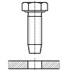
Self-tapping screws for metric ISO threads - Part 2: Guide values for hole diameters
Thread run-outs and thread undercuts
Tapping screw connections - Guideline values for core hole diameters and use
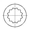
12 point socket for bolts and screws
60° centre holes - Types R. A. B. and C
Thread rolling screws for ISO metric thread guidelinge values for hole diameters
Thread ends and lengths of projection of bolt ends for metric ISO threads according to DIN 13
Knurle
Connections for hydraulic fluid power and general use - Ports and stud ends with ISO 261 metric threads and O-ring sealing - Part 1: Ports with truncated housing for O-ring

Hexalobular internal driving feature for bolts and screws
Connections for general use and fluid power - Ports and stud ends with ISO 228-1 threads with elastomeric or metal-to-metal sealing - Part 1: Threaded ports

Dimensioning and indication of knurling

Fasteners—Ends of parts with external ISO metric thread
Connections for general use and fluid power - Ports and stud ends with ISO 228-1 threads with elastomeric or metal-to-metal sealing - Part 4: Stud ends for general use only with metal-to-metal sealing (type B)

Hexalobular internal driving feature for bolts and screws
Geometrical product specifications (GPS) - Indication of surface texture in technical product documentation

General purpose bolts and screws─Metric series─Radii under the head

Rivet shank diameters
Aerospace - Spline drives - Wrenching configuration - Metric series
Connections for general use and fluid power - Ports and stud ends with ISO 261 threads with elastomeric or metal-to-metal sealing - Part 1: Threaded ports
Connections for general use and fluid power - Ports and stud ends with ISO 261 threads with elastomeric or metal-to-metal sealing - Part 2: Stud ends with elastomeric sealing (type E)
Connections for general use and fluid power - Ports and stud ends with ISO 261 threads with elastomeric or metal-to-metal sealing - Part 3: Stud ends with metal-to-metal sealing (type B)
Connections for general use and fluid power - Ports and stud ends with ISO 725 threads and O-ring sealing - Part 3: Light-duty (L series) stud ends

Fasteners—Surface discontinuities— Part2:Nuts

Countersunk flat hed screws—Part 2:Penetration depth of cross recesses

Fasteners—Surface discontinuities— Part3:Bolts,screw and studs for special requirements
Internal drive, offset cruciform recess (Torq-Set) for rotary fastening devices. Metric series

Fasteners—Thread undercuts for external metric ISO
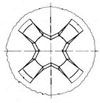
Cross recessed-H type

Cross recessed-Z type

Countersunk head screws—Head configuration and guaging

Fasteners—Hexagon products—Widths across flats

Fasteners─Clearance holes for bolts and screws

Thread run-out for fasteners with thread in accordance with ISO 261 and ISO 262
Copper tubes of circular section - Dimensions
Hexalobular internal driving feature for bolts and screws
Stress area and bearing area for threaded fasteners
General purpose bolts and screws - Metric series -- Radii under the head
Straight cylindrical involute splines -- side fit -- Generalities, dimensions and inspection
Knurling
Automatic Cold Header - Hole Size
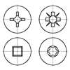
Recess Dimensions for Flat 82° Countersunk Head Screws
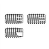
Dimensions of Threads and Points for Types BF and BT Thread-Cutting Tapping Screws
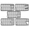
Dimensions of Threads and Points for Type D, F, G, and T Thread-Cutting Tapping Screws
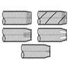
Dimensions of Type TRS Tapping Screws
Standard Test-Plate Thickness and Hole Sizes for Drive-Test Inspection of Tapping Screws


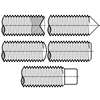
Dimensions of Alternate Styles of Points for Thumb and Wing Screws
Hot rolled flat steel bars and steel wide flats for general purposes - Dimensions and tolerances on shape and dimensions
Cold Rolled Uncoated and Zinc or Zinc-Nickel Electrolytically Coated Low Carbon and High Yield Strength Steel Flat Products for Cold Forming - Tolerances on Dimensions and Shape
Aerospace series - Installation holes for inserts, screw thread, helical coil, self-locking - Design standard
Countersunk head screws - Head configuration and gauging
Tapping rivats - Thread and end
Fasteners - Clearanc holes for bolts and screws
Cross Recesses For Screws
Standard Test-Plate Thickness and Hole Sizes for Drive-Test Inspection of Tapping Screws
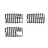
Dimensions of Threads and Points for Types BF and BT Thread-Cutting Tapping Screws
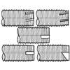
Dimensions of Threads and Points for Type D, F, G, and T Thread-Cutting Tapping Screws
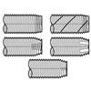
Type TRS Tapping Screws
Dimensions of Hexagon Sockets [Table 18]
![Body and grip lengths for socket head cap screws [Table 4]](https://imgcc.164580.com/upload/48/pic/2021/05/27/1622102178590886964.jpg)
Body and grip lengths for socket head cap screws [Table 4]
Metic threads and points for tapping screws
![Type BF and BT, Thread Cutting Tapping Screws [Table 7]](https://imgcc.164580.com/upload/48/standard/2020/06/05/1591322143016742879.jpg)
Type BF and BT, Thread Cutting Tapping Screws [Table 7]
![Type D,F,G and Type T Thread Cutting Tapping Screws [Table 8]](https://imgcc.164580.com/upload/48/standard/2020/06/05/1591326271806674189.jpg)
Type D,F,G and Type T Thread Cutting Tapping Screws [Table 8]
Aerospace series - Six lobe recess - Dimensions and tolerances
Threaded ends of fitting
