|
| No dimensional drawings!
Unit:
|
|
|
| No dimensional drawings!
Unit:
|
4 标记、标志和表面精饰
4.1 标记
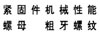
螺母的不锈钢组别和性能等级的标记制度,见图1。材料标记由短划隔开的两部分组成。第一部分标记钢的组别,第二部分标记性能等级。
不锈钢的组别(第一部分)标记,由一个字母和数字组成,其中:
——A是奥氏体钢;
——C是马氏体钢;
——F是铁素体钢。
字母表示钢的类别,数字表示该类钢的化学成分范围(见表1)。
性能等级(第二部分)标记:对螺母高度m≥0.8D(1型或2型或六角法兰螺母)的螺母,由两个数字组成,并表示保证应力的1/10;对螺母高度0.5D ≤m< 0.8D(薄螺母/0型)的螺母由3个数字组成,第一位数字“O”表示降低承载能力的螺母,后两位数字表示保证应力的1/10。以下是材料标记示例:
示例1:A2-70表示:奥氏体钢、冷加工、最小保证应力为700 MPa(m≥0.8D螺母)。
示例2:C4-70表示:马氏体钢、淬火并回火、最小保证应力为700 MPa(m≥0.8D螺母)。
示例3:AZ-035表示:奥氏体钢、冷加工、朵小保证应力为350 MPa(0.5D≤m<0.8D螺母)。
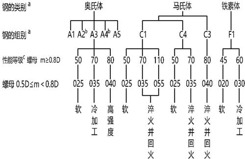
a 图中钢的类别和组别的分级,在附录B中说明,化学成分按表1规定。
b 含碳量低于0.03%的低碳奥氏体不锈钢可增加标记“L”。
示例:A4L-80
c 按GB/T 5267.4进行表面钝化处理,可以增加标记“P”。
示例:A4-80P
图1 螺母不锈钢组别和性能等级标记制度
4.2 标志
4.2.1 通则
按本部分制造的螺母,应按4.1标记制度和4.2.2与4.2.3或4.2.4进行标志。然而,4.1和4.2.3的规定只能用于符合本部分所有技术要求的产品。
注:对左旋螺纹的标志,按GB/T 3098.2的规定。
4.2.2 制造者识别标志
制造者识别标志应在生产过程中,在标志性能等级代号的所有螺母产品上进行标志,只要技术上可行,应尽可能提供。也推荐在不标志性能等级的螺母产品上标志制造者识别标志。紧固件销售者使用自己的识别标志,也应视为制造者识别标志。
4.2.3 螺母
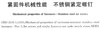
螺纹公称直径D≥5 mm的螺母应按4.1、图1和图2或图3进行清晰的标志。该标志是强制性的,并应包括钢的组别和性能等级。可以仅在螺母的一个支承面上标志,并只能用凹字。也允许在螺母侧面进行标志。
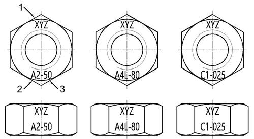
说明:1—制造者识别标志;2—钢的组别;3—性能等级。
图2 材料和制造者识别标志
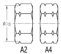
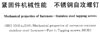
说明:S—对边宽度。
图3 可选用的刻槽标志(仅适用于A2和A4组钢)
当采用刻槽标志(见图3)时,因无法表示性能等级,其性能等级为:50或025级。
对细牙螺纹或螺母的几何原因,造成不能满足保证载荷要求的螺母产品,可以标志钢的组别,但不应标志性能等级。
4.2.4 包装
对各类螺母、所有规格的所有包装上,均应有标志(例如贴或拴标签)。标志或标签应包括制造者和/或经销者商标(或识别标志)和按图1对钢的组别和性能等级的标志代号,以及GB/T 90.3规定的生产批号。
4.3 表面精饰
除非另有规定,否则符合本部分的螺母应进行清洁和抛光。推荐最大限度的采用耐腐蚀、钝化处理。当要求钝化时,则应按GB/T 5267.4的规定进行。要求钝化处理的紧固件可以在其组别和性能等级(见图1的图注c)之后增加标志代号“P”。
按特殊定单制造的螺母,该附加标志既适用于螺母产品,也适用于标签。从仓库发送的螺母,该附加标志仅适用于标签。
5 化学成分
按本部分生产的螺母适用的不锈钢化学成分在表1中给出。
注:表1给出的化学成分与GB/T3098.6-2014 表1有关的钢的组别化学成分是一致的。
除非之前购买者与制造者另有协议,否则在规定的钢的组别范围内,化学成分由制造者选择。
在有晶间腐蚀倾向的场合,推荐按GB/T 4334的规定进行试验。在此情况下,推荐采用稳定型的A3和A5,或者采用含碳量不超过0.03%的A2和A4不锈钢。
表1 不锈钢组别与化学成分
类别 | 组别 | 化学成分a(质量分数)/% | 注 | ||||||||||
C | Si | Mn | P | S | N | Cr | Mo | Ni | Cu | W |
| ||
奥氏体 | A1 | 0.12 | 1 | 6.5 | 0.2 | 0.15~0.35 |
| 16~19 | 0.7 | 5~10 | 1.75~2.25 | — | b,c,d |
A2 | 0.10 | 1 | 2 | 0.05 | 0.03 |
| 15~20 | —e | 8~19 | 4 | — | f,g | |
A3 | 0.08 | 1 | 2 | 0.045 | 0.03 |
| 17~19 | —e | 9~12 | 1 | — | h | |
A4 | 0.08 | 1 | 2 | 0.045 | 0.03 |
| 16~18.5 | 2~3 | 10~15 | 4 | — | g,i | |
A5 | 0.08 | 1 | 2 | 0.045 | 0.03 |
| 16~18.5 | 2~3 | 10.5~14 | 1 | — | h,i | |
马氏体 | C1 | 0.09~0.15 | 1 | 1 | 0.05 | 0.03 |
| 11.5~14 | — | 1 | — | — | i |
C3 | 0.17~0.25 | 1 | 1 | 0.04 | 0.03 |
| 16~18 | — | 1.5~2.5 | — | — | — | |
C4 | 0.08~0.15 | 1 | 1.5 | 0.06 | 0.15~0.35 |
| 12~14 | 0.6 | 1 | — | — | b,i | |
铁素体 | F1 | 0.12 | 1 | 1 | 0.04 | 0.03 |
| 15~18 | —j | 1 | — | — | k,l |
注1:不锈钢的类别和组别,以及涉及其特性和应用的说明,在附录A中给出。 注2:按ISO 683-13和ISO 4954已标准化的不锈钢材料示例,在附录B和附录C中分别给出。 注3:某些特殊用途的材料,在附录D中给出。 | |||||||||||||
a 除已表明者外,均系最大值。 b 硫可用硒代替。 c 如镍含量低于8%,则锰的最小含量应为5%。 d 镍含量大于8%时,对铜的最小含量不予限制。 e 由制造者决定可以有钼含量。但对某些使用场合,如有必要限定钼的极限含量时,则应在订单中由用户注明。 f 如果铬含量低于17%,则镍的最小含量应为12%。 g 对最大含碳量达到0.03%的奥氏体不锈钢,氮含量最高可以达到0.22%。 h 为了稳定组织,钛含量应≥(5×C%)~0.8%,井应按本表适当标志,或者铌和/或钽含量应≥(10×C%)~1.0%,并应按本表适当标志。 i 对较大直径的产品,为达到规定的机械性能,由制造者决定可以用较高的含碳量,但对奥氏体钢不应超过0.12%。 j 由制造者决定可以有钼含量。 k 钛含量可能为≥(5×C%)~0.8%。 l 铌和/或钽含量≥(10×C%)~1.0%。 | |||||||||||||
6 机械性能
按本部分生产的螺母的机械性能,应符合表2和表3给出的数值。
本章规定的机械性能适用于验收检查,并应进行以下试验:
——硬度试验按7.1(仅适用于淬火并回火的Cl、C3和C4);
——保证载荷试验按7.2。
注:虽然本部分规定了很多种性能等级,但并非所有等级均适用于所有螺母。产品标准中规定的性能等级,可供非标准螺母参考。
表2 螺母机械性能——奥氏体钢组
类别 | 组别 | 性能等级 | 保证应力 SP/MPa | ||
螺母 m≥0.8D | 螺母 0.5D≤m<0.8D | 螺母 m≥0.8D | 螺母 0.5D≤m<0.8D | ||
奥氏体 | A1、A2、A3、A4、A5 | 50 | 025 | 500 | 250 |
70 | 035 | 700 | 350 | ||
80 | 040 | 800 | 400 | ||
表3 螺母机械性能-马氏体和铁素钢组
类别 | 组别 | 性能等级 | 保证应力 SP/MPa | 硬度 | ||||
螺母 m≥0.8D | 螺母 0.5D≤m<0.8D | 螺母 m≥0.8D | 螺母 0.5D≤m<0.8D | HB | HRC | HV | ||
马氏体 | C1 | 50 | 025 | 500 | 250 | 147~209 | / | 155~220 |
70 | / | 700 | / | 209~314 | 20~34 | 220~330 | ||
110a | 055a | 1100 | 550 | / | 36~45 | 350~440 | ||
C3 | 80 | 040 | 800 | 400 | 228~323 | 21~35 | 240~340 | |
C4 | 50 | / | 500 | / | 147~209 | / | 155~220 | |
70 | 035 | 700 | 350 | 209~314 | 20~34 | 220~330 | ||
铁素体 | F1b | 45 | 020 | 450 | 200 | 128~209 | / | 135~220 |
60 | 030 | 600 | 300 | 171~271 | / | 180~285 | ||
a 淬火并回火,最低回火温度为275℃。 b 螺纹公称直径D≤24 mm。 | ||||||||
7 试验方法
7.1 硬度HB、HRC或HV
马氏体和铁素体钢螺母的硬度试验,应按GB/T 231.1(HB)、GB/T 230.1(HRC)或GB/T 4340.1(HV)进行。如有争议,应以维氏硬度为验收依据。
试验程序与GB/T 3098.2的相同。
硬度值应在表3规定的范围内。
7.2 保证载荷
试验程序和判定应按GB/T 3098.2的规定。
(摘自ISO683-13:1986)
表B.1不锈钢成分技术条件
钢的类型a | 化学成分b (质量分数)— % | 钢的组别标记d | |||||||||||||
C | Si max | Mn max | P max | S | N | Al | Cr | Mo | Nbc | Ni | Se min | Ti | Cu | ||
铁素体钢 | |||||||||||||||
8 | 0.08 max | 1.0 | 1.0 | 0.040 | 0.030 max | — | — | 16.0~18.0 | — | — | 1.0 max | — | — | — | F1 |
8b | 0.07 max | 1.0 | 1.0 | 0.040 | 0.030 max | — | — | 16.0~18.0 | — | — | 1.0 max | — | 7×% C≤1.10 | — | F1 |
9c | 0.08 max | 1.0 | 1.0 | 0.040 | 0.030 max | — | — | 16.0~18.0 | 0.9~1.3 | — | 1.0 max | — | — | — | F1 |
F1 | 0.025 maxe | 1.0 | 1.0 | 0.040 | 0.030 max | 0.025 maxe | — | 17.0~19.0 | 1.75~2.5 | —f | 0.60 max | — | —f | — | F1 |
马氏体钢 | |||||||||||||||
3 | 0.09~0.15 | 1.0 | 1.0 | 0.040 | 0.030 max | — | — | 11.5~13.5 | — | — | 1.0 max | — | — | — | C1 |
7 | 0.08~0.15 | 1.0 | 1.5 | 0.060 | 0.15~0.35 | — | — | 12.0~14.0 | 0.060 max g | — | 1.0 max | — | — | — | C4 |
4 | 0.16~0.25 | 1.0 | 1.0 | 0.040 | 0.030 max | — | — | 12.0~14.0 | — | — | 1.0 max | — | — | — | C1 |
9a | 0.10~0.17 | 1.0 | 1.5 | 0.060 | 0.15~0.35 | — | — | 15.5~17.5 | 0.60 max g | — | 1.0 max | — | — | — | C3 |
9b | 0.14~0.23 | 1.0 | 1.0 | 0.040 | 0.030 max | — | — | 15.0~17.5 | — | — | 1.5~2.5 | — | — | — | C3 |
5 | 0.26~0.35 | 1.0 | 1.0 | 0.040 | 0.030 max | — | — | 12.0~14.0 | — | — | 1.0 max | — | — | — | C1 |
奥氏体钢 | |||||||||||||||
10 | 0.03 max | 1.0 | 2.0 | 0.045 | 0.030 max | — | — | 17.0~19.0 | — | — | 9.0~12.0 | — | — | — | A2h |
11 | 0.07 max | 1.0 | 2.0 | 0.045 | 0.030 max | — | — | 17.0~19.0 | — | — | 8.0~10.0 | — | — | — | A2 |
15 | 0.08 max | 1.0 | 2.0 | 0.045 | 0.030 max | — | — | 17.0~19.0 | — | — | 9.0~12.0 | — | 5×% C≤0.08 | — | A3i |
16 | 0.08 max | 1.0 | 2.0 | 0.045 | 0.030 max | — | — | 17.0~19.0 | — | 10×% C≤1.0 | 9.0~12.0 | — | — | — | A3i |
17 | 0.12max | 1.0 | 2.0 | 0.060 | 0.15~0.35 | — | — | 17.0~19.0 | —j | — | 8.0~10.0k | — | — | — | A1 |
18 | 0.10 max | 1.0 | 2.0 | 0.045 | 0.030 max | — | — | 17.0~19.0 | — | — | 11.0~13.0 | — | — | — | A2 |
19 | 0.03 max | 1.0 | 2.0 | 0.045 | 0.030 max | — | — | 16.5~18.5 | 2.0~2.5 | — | 11.0~14.0 | — | — | — | A4 |
20 | 0.07 max | 1.0 | 2.0 | 0.045 | 0.030 max | — | — | 16.5~18.5 | 2.0~2.5 | — | 10.5~13.5 | — | — | — | A4 |
21 | 0.08 max | 1.0 | 2.0 | 0.045 | 0.030 max | — | — | 16.5~18.5 | 2.0~2.5 | — | 11.0~14.0 | — | 5×% C≤0.08 | — | A5i |
23 | 0.08 max | 1.0 | 2.0 | 0.045 | 0.030 max | — | — | 16.5~18.5 | 2.0~2.5 | 10×% C≤1.0 | 11.0~14.0 | — | — | — | A5i |
19a | 0.03 max | 1.0 | 2.0 | 0.045 | 0.030 max | — | — | 16.5~18.5 | 2.5~3.0 | — | 11.5~14.5 | — | — | — | A4 |
20a | 0.07 max | 1.0 | 2.0 | 0.045 | 0.030 max | — | — | 16.5~18.5 | 2.5~3.0 | — | 11.0~14.0 | — | — | — | A4 |
10N | 0.03 max | 1.0 | 2.0 | 0.045 | 0.030 max | 0.12~0.22 | — | 17.0~19.0 | — | — | 8.5~11.5 | — | — | — | A2 |
19N | 0.03 max | 1.0 | 2.0 | 0.045 | 0.030 max | 0.12~0.22 | — | 16.5~18.5 | 2.0~2.5 | — | 10.5~13.5 | — | — | — | A4h |
19aN | 0.03 max | 1.0 | 2.0 | 0.045 | 0.030 max | 0.12~0.22 | — | 16.5~18.5 | 2.5~3.0 | — | 11.5~14.5 | — | — | — | A4h |
a 类型编号是暂定的,当制定有关的国际标准时,还会改变。 b 本表未列出的元素,未经用户同意,不能增加,除非要精炼。应采取合理的预防措施,以防止某些元素(来自制造过程中混入的废料或其他金属)的增加,因为这些元素会影响材料的淬透性、机械性能和使用性能。 c 钽含量取决于铌含量。 c 不是ISO 683—13的内容。 e (C+N)max为0.040%。 f 8×(C+N)≤(Nb+Ti)≤0.80%。 g 在询问和签约订单之后,可能提供Mo含量为0.20%~0.60%的钢。 h 有极好的耐晶间腐蚀性。 i 稳定型钢。 j 制造者可选择添加最大到0.70%的钼。 k 对制造无缝钢管的半成品,镍含量可能增加0.5%。 | |||||||||||||||
氯化物导致的奥氏体不锈钢应力腐蚀
[摘自EN10088-1:2005]
因氯化物导致应力腐蚀(如室内游泳池)造成螺栓、螺钉和螺柱失效的风险,可通过使用表D.1给出的材料而降低。
表D.1氯化物导致的奥氏体不锈钢应力腐蚀
奥氏体不锈钢 (代号/材料编号) | C max | Si max | Mn max | P max | S max | N | Cr | Mo | Ni | Cu |
X2CrNiMoN17-13-5 (1.4439) | 0.030 | 1.00 | 2.00 | 0.045 | 0.015 | 0.12~0.22 | 16.5~18.5 | 4.0~5.0 | 12.5~14.5 |
|
X1NiCrMoCu25-20-5 (1.4539) | 0.020 | 0.70 | 2.00 | 0.030 | 0.010 | ≤0.15 | 19.0~21.0 | 4.0~5.0 | 24.0~26.0 | 1.20~2.00 |
X1NiCrMoCuN25-20-7 (1.4529) | 0.020 | 0.50 | 1.00 | 0.030 | 0.010 | 0.15~0.25 | 19.0~21.0 | 6.0~7.0 | 24.0~26.0 | 0.50~1.50 |
X2CrNiMoN22-5-3a (1.4539) | 0.030 | 1.00 | 2.00 | 0.035 | 0.015 | 0.10~0.22 | 21.0~23.0 | 2.5~3.5 | 4.5~6.5 |
|
a 铁素体-奥氏体不锈钢。 | ||||||||||
高温下的机械性能和低温下的适用性
注:如果螺栓、螺钉或螺柱经过计算认为是合格的,则相匹配的螺母也会符合要求。因此,在用于高温或低温的情况下,只要充分考虑螺栓、螺钉或螺柱的机械性能即可。
E.1 高温下的下屈服强度或规定塑性延伸率为0.2%时的应力
本附录给出的数值仅是指导性的。使用者应当明白,实际的化学成分和性质、安装紧固件的载荷及环境都可能产生很大的变化。如果在高温下载荷是循环交变的、是大的或高的应力腐蚀的可能性,使用者应向制造者咨询。
在高温条件下,下屈服强度和规定塑性延伸率为0.2%时的应力数值与室温下的数值之比(用%表示),见表E.1。
表E.1受温度影响的ReL和RP0.2
钢的组别 | ReL和R p0.2/% | |||
+100℃ | +200℃ | +300℃ | +400℃ | |
A2、A4 | 85 | 80 | 75 | 70 |
C1 | 95 | 90 | 80 | 65 |
C3 | 90 | 85 | 80 | 60 |
注:仅适用于性能等级70和80。 | ||||
E.2 低温下的适用性
低温下不锈钢紧固件的适用性,见表E.2。
表E.2 低温下不锈钢螺栓、螺钉和螺柱的适用性(奥氏体不锈钢)
钢的组别 | 持续工作温度/min | |
A2、A3 | -200℃ | |
A4、A5 | 螺栓和螺钉a | -60℃ |
螺柱 | -200℃ | |
a 加工变形量较大的紧固件时,应考虑合金元素Mo能降低奥氏体的稳定性,并提高脆性转变温度的问题。 | ||
奥氏体不锈钢的相对导磁率
有特殊磁性要求的场合,应向有经验的金属学专家咨询。
所有奥氏体不锈钢紧固件在固熔状态下,通常是无磁的;经冷变形加工后,有些会呈现明显的磁性。
各种材料被磁化能力的特性,也适用于不锈钢。只有在真空状态下才有可能完全无磁。磁场中材料的相对磁导率的测量是相对于材料在真空中的相对磁导率μr而言。如果μr接近1,则该材料具有低的相对磁导率。
示例1: A2: μr≈1.8
示例2: A4: μr≈1.015
示例3: A4L:μr≈1.005
示例4: F1: μr≈5
Mechanical properties of fasteners - Stainless steel Bolts, screws and studs
Mechanical properties of fasteners-Stainless steel and nickel alloys bolts, screws, studs and nuts for high temperature applications
Mechanical properties of fasteners-Guidance for the selection of stainless steels and nickel alloys for fasteners
Mechanical Properties of Fasteners - Prevailing Torque Type Steel Nuts
Mechanical properties of fasteners-Set screws
Mechanical properties of fasteners-nuts with coarse thread
High-strength structural bolting assemblies for preloading - Part2: Suitability for preloading
Mechanical properties of fasteners - Stainless steel set screws
Mechanical properties of fasteners - Stainless steel Bolts, screws and studs
Mechanical properties of fasteners-Bolts、screws and studs

Mechanical properties of fasteners Parts for bolted connections for use at temperatures from -200 ℃~+700 ℃
Mechanical properties of fasteners made of the fine grain non-heat treatment steel-Bolts,screws and studs
Spring washer technical conditions
Mechanical properties of fasteners-Blind rivets
Mechanical properties of fasteners. Wing nuts with specified proof torque
Mechanical properties of fasteners-Drilling screws with tapping screws thread
Mechanical properties of fasteners. Prevailing torque type steel hexagon nuts
Mechanical properties of fasteners-Nuts-Fine pitch thread
Mechanical propretles of fasteners tapping screws
Mechanical properties of fasteners-Bolts、screws and studs made of stainless-steel
Machanical properties of fasteners-Thread rolling screws
Mechanical properties of fasteners Bolts,scrows,studs and nuts made of non-ferrous metals
Specification for revit
Mechanical Properties of Fasteners 一 Tapping Screws
Fasteners - Mechanical properties of corrosion-resistant stainless steel fasteners - Part 7: Flat washers with specified grades and property classes
Heat treated tapping screws - Mechanical and physical properties
Mechanical properties of fasteners made of carbon steel and alloy steel — Part 2: Nuts with specified property classes
Mechanical properties of corrosion-resistant stainless steel fasteners - Nuts with specified grades and property classes bsi.
Mechanical properties of fasteners made of carbon steel and alloy steel – Part 3: Flat washers with specified property classes
Mechanical Properties of Fasteners - Prevailing Torque Type Steel Nuts
Mechanical properties of fasteners made of carbon steel and alloy steel. Part 1:Bolts,screws and studs with specified property classes. Coarse thread
Mechanical properties of fasteners made of carbon steel and alloy steel - Part 2: Nuts with specifed property classes - Coarse thread and fne pitch thread
Mechanical properties—Set screw and similar threaded fasteners with specified hardness classes
Heat-treated steel tapping screws - Mechanical properties
Mechanical properties of corrosion resistant stainless steel fasteners—Part 1:Nuts
Mechanical properties of corrosion resistant stainless steel fasteners— Part 3:Set screws and similar fasteners not under tensile stress
Mechanical properties of corrosion resistant stainless steel fasteners— Part 4:Tapping screws
Drilling screws with tapping screw thread— Mechanical and functional properties
Mechanical and performance requirements of case hardened and tempered metric thread rolling screws
Mechanical properties of fasteners - Part 6: Nuts with specified proof load values - Fine pitch thread
Torsional test and minimum torques for bolts and screws
Mechanical properties of fasteners—Bolts,screws,studs and nuts made of non-ferrous metals
Heat-treated steel tapping screws - Mechanical properties
Test methods of tightening torque for bolts
Maximum Drive Torque for Type TRS Tapping Screws
Torsional Strength Requirements for Tapping Screws
Nylon Insert Locknuts (Inch Series)
Aerospace series - Bolts, MJ threads, in heat resisting steel FE-PA2601 (A286) - Classification: 900 MPa (at ambient temperature)/650℃ - Technical specification
Non-preloaded structural bolting assemblies - Part 1: General requirements
High-strength structural bolting assemblies for preloading - Part 2: Suitability for preloading
Mechanical properties of fasteners - Part 7: Torsional test and minimum torques for bolts and screws with nominal diameters 1 mm to 10 mm
Mechanical properties of fasteners - Part 2: Nuts with specified proof load values - Coarse thread
Mechanical properties of fasteners - Part 6: Nuts with specified proof load values - Fine pitch thread
Mechanical properties of fasteners - Part 1: Bolts, screws and studs
Mechanical Properties of Fasteners - Bolts, Screws, Studs and Nuts
Suppliers(1)
Carbon Steel Bolts, Studs, and Threaded Rod 6000 PSI Tensile Strength
Carbon steels、alloy steels and stainless materials for bolts and nuts
Mechanical properties of fasteners made of carbon steel and alloy steel Part 2: Nuts with specified property classes - Coarse thread and fine pitch thread
Mechanical properties of fasteners made of carbon steel and alloy steel. Part 1:Bolts,screws and studs
Self-drilling screws for the building and construction industries Part 1: General requirements and mechanical properties
Thread Rolling Screws
Maximum Drive Torque for Type TRS Tapping Screws
Torsional Strength Requirements for Tapping Screws